The Inverter: The Unsung Hero of an EV Drivetrain
As you know, electric vehicles have one or more batteries, and one or more propulsion motors. Our designs use a single propulsion motor which connects via a simple transmission unit to the vehicle’s drive shaft. But have you ever wondered what goes in-between the batteries and the motor?
Just like the AA batteries in your flashlight, the batteries in an EV are DC (direct current) devices, which means that there’s a positive terminal and a negative terminal, and the voltages on these terminals are steady. OK, unlike your AA batteries, our batteries generate hundreds of volts and lots of current; but they still have “+” and “-” connections.
In theory, one could simply connect the power from these batteries to a DC motor, which is a motor that operates on a steady voltage. However, DC motors aren’t a good solution for EV applications because they’re hard to control precisely for speed and torque. After all, the motor in an EV has to operate smoothly and predictably from zero RPM (vehicle not moving) to hundreds of RPM (on the highway). This level of control is best achieved with an AC (alternating current) motor. Alternating current changes its voltage all the time in a cyclic way. It’s what comes out of your 110V or 220V outlets at home.
So – somehow – we need to take the high-voltage, high-current DC electricity that comes from the batteries and convert it to AC electricity for the motor. That’s where the inverter comes in.
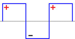
An inverter is an electronic device which uses power transistors as switches to slice and dice the DC electricity to create an AC output. AC has positive and negative voltages in its cycle, and the transistors open and close connections which alternately allow the voltage through unchanged or make it negative (hence the name “inverter”). In its simplest form, the output would be a “square wave”:
However, the AC electricity that comes from your home’s outlets takes the form of a “sine wave”:
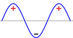
A sine wave has a much smoother variation between positive and negative, and it’s a lot more suitable for AC motors, which have magnetic fields inside them which need time to rise and fall in strength.
By switching the transistors on and off very rapidly, the output voltages can be “constructed” by mixing short bursts of positive and negative volts in varying amounts to give an average voltage that follows the sine wave (“sinusoidal”) shape. This technique is called “pulse width modulation”. Adding some “filtering”, which consists of electronic components that smooth the signal out, can produce a pure sinusoidal AC output.
But there’s more that the inverter in an EV has to do…
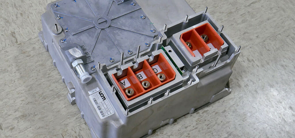
The AC motors we use are “three phase” motors, which means that they operate on three separate AC electrical currents which are offset from each other in time. This means that phase 2 reaches its positive peak a little after phase 1 does; and phase 3 reaches its peak a little after phase 2. It’s like a Stadium Wave of voltage. This has the effect in the motor of creating a set of magnetic fields which effectively rotate, which is what causes the rotor (the rotating part of the motor) to turn. Hence, the inverter in our EVs doesn’t produce just one AC output – it produces three. You can see in this photo that there’s a two-way connection for the DC input (+ and -), and three connectors for the AC cables that feed the motor:
But we’re not done yet: the inverter has another job to do…
The inverter in an EV is also what’s called a VFD – Variable Frequency Drive. The sine wave AC power can be generated in a wide range of different frequencies. Or in other words, the rate at which the voltage cycles from positive to negative and back again can be changed dramatically. This is what’s needed to control the rotation speed of the motor. By changing the AC frequency, that magnetic Stadium Wave speeds up or slows down, and the motor changes speed. And so does the vehicle. One of the great things about an electric motor is that it can generate useful propulsion torque over a very wide range of rotation speeds; this is quite different from a gasoline or diesel engine, which is one reason why they need complex multi-speed transmissions.
We’ve seen that the inverter converts DC electricity into cleverly constructed, smoothly sinusoidal, three-phase, variable-frequency AC power. So, are we done yet?
Nope. There’s “regen” too.
Regen – short for “regeneration” – is the behavior of EVs where when you take your foot off the accelerator pedal, the motor becomes a generator which sends charge to the batteries. This helps to improve the range on the road – and to extend the lifetime of your brake components. So, when the motor is acting as a generator, it produces three phases of sinusoidal AC power. The inverter has to take these and convert them to a single DC output which has a higher voltage than the batteries, in order to charge them.
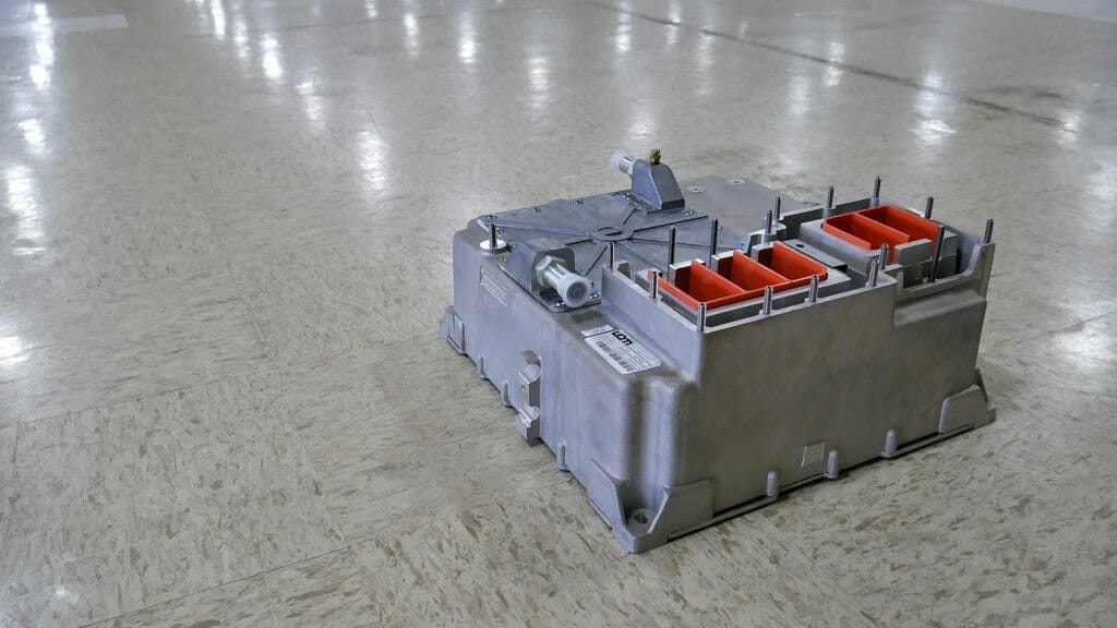
The photos in this article show an inverter from our partner UQM (now Danfoss Editron), which we employ in our new 2nd generation Ford Transit powertrain. UQM doesn’t just supply the inverter, but also the permanent-magnet motor and the clever control software embedded in the inverter. Supplying the whole system like this lets them optimize it for best torque and efficiency with low weight, which makes it a great fit for the Transit platform.
So you see that the inverter is a sophisticated piece of equipment which is the unsung hero of the electric vehicle’s drivetrain.